三、外部接口应用指南
3.1 概述
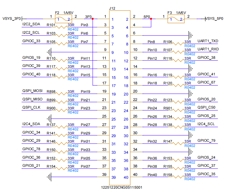
EM20-DK 开发板外部接口有电源、I2C、UART、GPIO 和 QSPI 信号。其中有 2 路 3.3V 电压,1 路 5V 电压,8 个接地。
3.1.1 接口图
如下所示:
3.1.2 电源信号
| Pin | Signal Name | Function | Voltage |
|---|---|---|---|
| 1 | VSYS_3P3 | 3.3V power supply | 3.3V |
| 2 | VSYS_5P0 | 5.0V power supply | 5.0V |
| 17 | VSYS_3P3 | 3.3V power supply | 3.3V |
3.1.3 I2C接口
3.1.3.1 I2C2 接口
| Pin | Signal Name | Function | Electrical Specs |
|---|---|---|---|
| 3 | I2C2_SDA | I2C2 data line | 3.3V logic, bidirectional, 400kbps max |
| 5 | I2C2_SCL | I2C2 clock line | 3.3V logic, bidirectional, 400kbps max |
3.1.3.2 I2C4 接口
| Pin | Signal Name | Function | Electrical Specs |
|---|---|---|---|
| 27 | I2C4_SDA | I2C4 data line | 3.3V logic, bidirectional, 400kbps max |
| 28 | I2C4_SCL | I2C4 clock line | 3.3V logic, bidirectional, 400kbps max |
3.1.4 UART 接口(UART1)
| Pin | Signal Name | Function | Electrical Specs |
|---|---|---|---|
| 8 | UART1_TXD | UART1 transmit data | 3.3V logic, TX output |
| 10 | UART1_RXD | UART1 receive data | 3.3V logic, RX input |
3.1.5 GPIO 信号
| Pin | Signal Name | Function | Default State | Electrical Type |
|---|---|---|---|---|
| 7 | GPIOC_33 | General - purpose I/O | Input | I/O |
| 11 | GPIOS_19 | General - purpose I/O | Input | I/O |
| 13 | GPIOC_39 | General - purpose I/O | Input | I/O |
| 15 | GPIOC_40 | General - purpose I/O | Input | I/O |
| 22 | GPIOS_20 | General - purpose I/O | Input | I/O |
| 26 | GPIOS_25 | General - purpose I/O | Input | I/O |
| 29 | GPIOC_34 | General - purpose I/O | Input | I/O |
| 31 | GPIOC_29 | General - purpose I/O | Input | I/O |
| 33 | GPIOC_78 | General - purpose I/O | Input | I/O |
| 35 | GPIOC_36 | General - purpose I/O | Input | I/O |
| 37 | GPIOS_21 | General - purpose I/O | Input | I/O |
| 39 | GND | Ground reference | - | Power |
| 40 | GPIOC_35 | General - purpose I/O | Input | I/O |
3.1.6 QSPI 接口
| Pin | Signal Name | Function | Electrical Specs |
|---|---|---|---|
| 19 | QSPI_MOSI | QSPI master - out - slave - in | 3.3V logic, data output |
| 21 | QSPI_MISO | QSPI master - in - slave - out | 3.3V logic, data input |
| 23 | QSPI_CLK | QSPI clock | 3.3V logic, master - generated clock |
| 24 | QSPI_CS0 | QSPI chip select 0 | 3.3V logic, active low |
3.2 I2C 使用
提供了 2 路 I2C(IIC2 和 IIC4)可让用户自由使用,可以使用标准的 I2C tools 和 API 操作(i2c接口的验证,请参考 「40pin Sample」章节 的相关内容)。
- i2cdetect命令输出已安装I2C总线的列表(以其他路 I2C 作为演示使用):
root@taco-dk:~# i2cdetect -l
i2c-0   i2c             Cadence I2C at d2400000               I2C adapter
i2c-1   i2c             Cadence I2C at d2401000               I2C adapter
i2c-2   i2c             Cadence I2C at c2401000               I2C adapter
- i2cset 配置 i2c 外设
i2cset -f -y $I2C_BUS $I2C_ADDR $reg $value
- i2cget 获取 i2c 外设的值
i2cget -f -y $I2C_BUS $I2C_ADDR $reg
参数解释:
$I2C_BUS:I2C 总线号。在 40pin 接插件中,此为 2 或 4(对应 IIC2,IIC4)
$I2C_ADDR:I2C 设备的地址,通过实际的 I2C 设置 SPEC 确认
$reg:寄存器地址,通过实际的 I2C 设置 SPEC 确认
$value:要写入的值。
以下为一个完整的python示例代码,展示如何使用 i2c:
def i2c_test():
    print("===== Starting I2C Test =====")

    # Get I2C bus number from user
    bus_num_input = input("Please enter I2C bus number: ")
    try:
        bus_num = int(bus_num_input)
    except ValueError:
        print("Error: Bus number must be an integer")
        return

    print(f"Scanning I2C bus {bus_num} for devices...")
    os.system(f'i2cdetect -y -r {bus_num}')

    dev_addr_hex = input("Please enter I2C device address: ")
    try:
        dev_addr = int(dev_addr_hex, 16)
    except ValueError:
        print("Error: Device address must be a hexadecimal number")
        return

    print(f"Reading data from device {hex(dev_addr)} on I2C bus {bus_num}...")

    try:
        bus = smbus.SMBus(bus_num)

        value = bus.read_byte(dev_addr)

        bus.write_byte(dev_addr, value)

        print(f"Read value: 0x{value:02x} (decimal: {value})")

    except IOError as e:
        print(f"I2C communication failed: {e} (check connection, address, or permissions)")
    except Exception as e:
        print(f"Error occurred: {e}")
    finally:
        if 'bus' in locals():
            bus.close()
函数说明:
- 列出所有设备
os.system(f'i2cdetect -y -r {bus_num}')
- 打开设备节点
bus = smbus.SMBus(bus_num)
- 读写
bus.read_byte(dev_addr)
...
bus.write_byte(dev_addr, value)
3.3 UART 使用
EM20-DK 提供了 1 路 UART(UART1)可让用户自由使用(uart口的验证,请参考 「40pin Sample」章节 的相关内容)。 以UART0(作为 debug 串口)为例,用户可以参照以下命令来操作UART设备节点来体验串口效果:
root@taco-dk:~# echo "Hello World" > /dev/ttyPS0
Hello World
以下是一个python示例代码,展示如何配置和使用 UART1 (此处硬件上需要将 UART1_RXD 和 UART1_TXD 连接起来,EM20-DK自发自收):
def serial_test():
    print("===== Starting Serial Test =====")

    print("Available serial devices:")
    os.system('ls /dev/tty[a-zA-Z]*')

    uart_dev = input("Please enter the serial device name to test: ")
    baudrate_input = input("Please enter baud rate (9600, 19200, 38400, 57600, 115200, 921600): ")

    try:
        ser = serial.Serial(uart_dev, int(baudrate_input), timeout=1)
        print(f"Successfully opened serial port: {ser}")
    except Exception as e:
        print(f"Failed to open serial port: {e}")
        return

    try:
        print("Starting communication test. Press CTRL+C to exit")
        while True:
            test_data = "AA55"
            write_num = ser.write(test_data.encode('UTF-8'))
            print(f"Sent: {test_data}")

            received_data = ser.read(write_num).decode('UTF-8', errors='replace')
            print(f"Received: {received_data}")

            time.sleep(1)
    except KeyboardInterrupt:
        pass
    finally:
        ser.close()
        print("Serial port closed")
函数说明:
- 打开设备节点 与 配置串口波特率
ser = serial.Serial(uart_dev, int(baudrate_input), timeout=1)
- 读写
  ser.write(test_data.encode('UTF-8'))
  ...
  ser.read(write_num).decode('UTF-8', errors='replace')
3.4 SPI 使用
EM20-DK 提供了 1 路 SPI(QSPI)可让用户自由使用(SPI口的验证,请参考 「40pin Sample」章节 的相关内容)。
以下是一个python示例代码,展示如何配置和使用SPI:
def spi_test():
    print("===== Starting SPI Test =====")

    print("Available SPI controllers:")
    os.system('ls /dev/spidev*')

    try:
        spi_bus = int(input("Please enter SPI bus number: "))
        spi_device = int(input("Please enter SPI chip select number: "))
    except ValueError:
        print("Error: Bus number and chip select must be integers")
        return

    spi = spidev.SpiDev()

    try:
        spi.open(spi_bus, spi_device)
        spi.max_speed_hz = 12000000
        print(f"Successfully opened SPI device: /dev/spidev{spi_bus}.{spi_device}, Frequency: 12MHz")

        print("Starting communication test. Press CTRL+C to exit")
        while True:
            resp = spi.xfer2([0x55, 0xAA])
            print(f"Received data: {bytes_to_hex(resp)}")
            time.sleep(1)
    except Exception as e:
        print(f"SPI operation failed: {e}")
    finally:
        spi.close()
        print("SPI device closed")
函数说明:
-
配置SPI相关配置
- 设置 spi_bus
- 设置 spi_device
- 设置 max_speed_hz
-
发送message,收发数据
resp = spi.xfer2([0x55, 0xAA])
3.5 GPIO 使用
芯片支持三组 GPIO ,分别命名为 SAP GPIO,CPU GPIO 和 RTC GPIO。在每个 GPIO 组内对信号从 0 开始编址,称为物理编号,此外,软件还对全部 GPIO 信号做了统一编址,称为逻辑编号,其编号规则是
GPIO 逻辑编号 = GPIO 所属组 BASE 号 + 组内物理编号
| GPIO 组别 | Linux 设备节点 | 物理编号范围 | 逻辑编号范围 |
|---|---|---|---|
| SAP GPIO | /sys/class/gpio/gpiochip0/ | 0 到 33 | 0 到 33 |
| CPU GPIO | /sys/class/gpio/gpiochip200/ | 0 到 142 | 200 到 342 |
| RTC GPIO | /sys/class/gpio/gpiochip400/ | 0 到 7 | 400 到 407 |
EM20-DK 提供了多个GPIO口供用户自由使用(GPIO口的验证,请参考 「40pin Sample」章节 的相关内容)。
以下是一个python示例代码,展示如何配置和使用GPIO:
def gpio_test():
    print("\n===== Starting GPIO Manual Control Test =====")

    domain = input("Please enter GPIO domain (cpu/rtc/sap): ").lower()
    if domain not in ['cpu', 'rtc', 'sap']:
        print("Error: Invalid domain. Must be 'cpu', 'rtc', or 'sap'")
        return

    domain_offset = 200 if domain == 'cpu' else 400 if domain == 'rtc' else 0

    try:
        base_num = int(input(f"Please enter base GPIO number (domain {domain}): "))
        gpio_num = base_num + domain_offset

    except ValueError:
        print("Error: GPIO number must be an integer")
        return

    gpio_path = f"/sys/class/gpio/gpio{gpio_num}"
    value_path = f"{gpio_path}/value"

    try:
        if not os.path.exists(gpio_path):
            with open("/sys/class/gpio/export", "w") as f:
                f.write(str(gpio_num))
            time.sleep(0.1)

        with open(f"{gpio_path}/direction", "w") as f:
            f.write("out")
        time.sleep(0.1)

        print("\nGPIO manual control mode:")
        print("Commands: '1' to set high, '0' to set low, 'q' to quit")

        while True:
            cmd = input("Enter command (1/0/q): ").strip().lower()
            if cmd == 'q':
                print("Exiting GPIO control")
                break
            elif cmd in ['0', '1']:
                with open(value_path, "w") as f:
                    f.write(cmd)
                time.sleep(0.1)

                with open(value_path, "r") as f:
                    read_val = f.read().strip()
                print(f"GPIO{gpio_num} set to {cmd}, verified value: {read_val}")
            else:
                print("Invalid command. Please enter '1', '0', or 'q'")

        print("\n===== GPIO Test Completed =====")
        return True

    except PermissionError:
        print("Error: Permission denied. Please run with root privileges (sudo)")
        return False
    except Exception as e:
        print(f"GPIO test failed: {str(e)}")
        return False
    finally:
        pass
3.6 LED 与 Button
此外,EM20-DK 支持在 40pin 脚上配置 LED 与 Button。
- LED
python3 -u /usr/data/gpiozero/gpio_control.py -t led -p 63 -a on
python3 -u /usr/data/gpiozero/gpio_control.py -t led -p 63 -a off
- Button
python3 -u /usr/data/gpiozero/gpio_control.py -t button -p 63 -a watch
参数说明:
-t: 指定 LED 或者 Button-p:引脚编号-d: 指定时间段,当指定 -a blink 时,需要指定-d参数-a: 指定动作,LED 的动作有on、off、toggle、blink;Button 的动作有watch、readon为点亮 LEDoff为熄灭 LEDtoggle为 LED 灯状态翻转blink为 LED 灯闪烁,其需要设定间隔闪烁参数watch为 Button 的监控read为 Button 的读取
3.7 播放音视频
3.7.1 使用 ffmpeg 播放视频流
插上 USB 摄像头,同时可购买配套的 MIPI 显示屏,并连接至对应接口,通过 ffmpeg 命令行抓流并播放。
例如播放 USB 摄像头的视频流:
# ffmpeg -f video4linux2 -i /dev/video0 -vf \"scale=1920:1080,format=rgb32\" -f fbdev /dev/fb1 &
3.7.2 使用 aplay 播放音频流
可将耳机线插入到 3.5mm 音频接口,然后通过 aplay 命令行播放 wav 文件,即可在耳机中听到声音。例如:
# aplay -D hw:0,0 -c 2 -f S16_LE -r 44100 /usr/data/sound/sound-test.wav